Content
Position, displacement and distance
In this module, we are only talking about motion in a straight line. For a horizontal line, there are only two directions to consider: right and left. For a vertical line, the two directions are up and down. We choose a point on the line, which we call the reference point or origin. For convenience, we will measure distance in metres and time in seconds.
Position
The line is coordinatised and referenced from a point , the origin. For a horizontal line, the convention is that positions to the right of are positive, and positions to the left are negative.
For example:
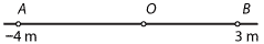
- The position of the particle at is 3 m.
- The position of the particle at is m.
The position of a particle is often thought of as a function of time, and we write for the position of the particle at time .
Displacement
The displacement of a particle moving in a straight line is the change in its position. If the particle moves from the position to the position , then its displacement is over the time interval . In particular, the position of a particle is its displacement from the origin.
For example:
- If a particle moves from to , its displacement is 3 m.
- If a particle moves from to , its displacement is m.
- If a particle moves from to , its displacement is 7 m.
- If a particle moves from to , its displacement is m.
Position and displacement are vector quantities, that is, they have both magnitude and direction. In this module, we are dealing with vectors in one dimension. The sign of the quantity (positive or negative) indicates its direction. The absolute value of the quantity is its magnitude.
Distance
The distance is the 'actual distance' travelled. Distances are always positive or zero.
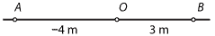
For example, given the following diagram, if a particle moves from to and then to , the displacement of the particle is 4 m, but the distance travelled is 10 m.
Example
A particle moves along a straight line so that its position at time seconds is metres, relative to the origin. Assume that , and , and that the particle only changes direction when . Find the distance travelled by the particle from time to time .Solution
The distance travelled is metres.Summary
- The position of a particle moving in a straight line is a vector which represents a point on the line in relation to the origin . The position of a particle is often thought of as a function of time, and we write for the position of the particle at time .
- The displacement of a particle moving in a straight line is a vector defined as the change in its position. If the particle moves from the position to the position , its displacement is for the time interval .
- The distance travelled by a particle is the 'actual distance' travelled.
What is the difference between distance and displacement?
- Distance is a scalar measure while displacement is a vector.
- Displacement is indicated with an arrow while distance is never indicated with an arrow.
- Distance only considers magnitude while displacement takes into account both magnitude and direction.
- Displacement can have both positive and negative values while distance can only have positive values.
- The symbol delta Δ is used for displacement while this is not the case for distance.
- Distance can be used to calculate speed given time, while displacement can be used to calculate velocity given change of distance (displacement), over time.
- Displacement is always measured along a straight line path, while distance can be measured along a non-straight path.
MEASUREMENT OD LENGTH (DISTANCE BETWEEN TWO POINTS)
SI unit for length is metre (m). It is a scalar quantity.
Things you need to know:
Accuracy refers to the maximum error encountered when a particular observation is made.
Error in measurement is normally one-half the magnitude of the smallest scale reading.
Because one has to align one end of the rule or device to the starting point of the measurement, the appropriate error is thus twice that of the smallest scale reading.
Error is usually expressed in at most 1 or 2 significant figures.

Tape
Equipment: It is made up of a long flexible tape and can measure objects or places up to 10 – 50 m in length. It has markings similar to that of the rigid rule. The smallest marking could be as small as 0.1 cm or could be as large as 0.5 cm or even 1 cm.
How to use: The zero-mark of the measuring tape is first aligned flat to one end of the object and the tape is stretched taut to the other end, the reading is taken where the other end of the object meets the tape.
Accuracy: ± 1 cm
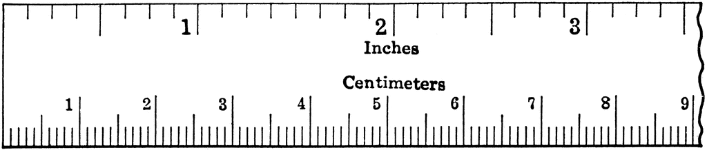
Rule
Equipment: It is made up of a long rigid piece of wood or steel and can measure objects up to 100 cm in length. The smallest marking is usually 0.1 cm.
How to use: The zero-end of the rule is first aligned flat with one end of the object and the reading is taken where the other end of the object meets the rule.
Accuracy: ± 0.1 cm

Vernier Caliper
Equipment: It is made up of a main scale and a vernier scale and can usually measure objects up to 15 cm in length. The smallest marking is usually 0.1 cm on the main scale.
It has:
a pair of external jaws to measure external diameters
a pair of internal jaws to measure internal diameters
a long rod to measure depths
How to use: The jaws are first closed to find any zero errors. The jaws are then opened to fit the object firmly and the reading is then taken.
Accuracy: ± 0.01 cm

Micrometer Screw Gauge
Equipment: It is made up of a main scale and a thimble scale and can measure objects up to 5 cm in length. The smallest marking is usually 1 mm on the main scale (sleeve) and 0.01 mm on the thimble scale (thimble). The thimble has a total of 50 markings representing 0.50 mm.
It has:
an anvil and a spindle to hold the object
a ratchet on the thimble for accurate tightening (prevent over-tightening)
How to use: The spindle is first closed on the anvil to find any zero errors ( use the ratchet for careful tightening). The spindle is then opened to fit the object firmly (use the ratchet for careful tightening) and the reading is then taken.
Accuracy: ± 0.01 mm
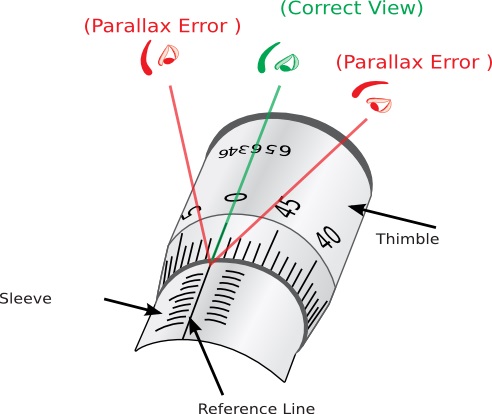
Parallax Error
For accurate measurement, the eye must always be placed vertically above the mark being read. This is to avoid parallax errors which will give rise to inaccurate measurement.
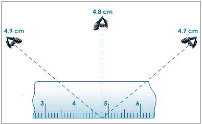
Parallax errors affects the accuracy of the measurement. If you consistently used the incorrect angle to view the markings, your measurements will be displaced from the true values by the same amount. This is called systematic error.
However, if you used different angles to view the markings, your measurements will be displaced from the true values by different amounts. This is called random error.
Parallax error for micrometer screw gauge:
Zero Error
Zero Errors of Vernier Caliper
When the jaws are closed, the vernier zero mark coincides with the zero mark on its fixed main scale.
Before taking any reading it is good practice to close the jaws or faces of the instrument to make sure that the reading is zero. If it is not, then note the reading. This reading is called “zero error”.
The zero error is of two types:
Positive zero error; and
Negative zero error.

Positive Zero Error
If the zero on the vernier scale is to the right of the main scale, then the error is said to be positive zero error and so the zero correction should be subtracted from the reading which is measured.

Negative Zero Error
If the zero on the vernier scale is to the left of the main scale, then the error is said to be negative zero error and so the zero correction should be added from the reading which is measured.
Zero Error for micrometer screw gauge

If the zero on the vernier scale is to the left of the main scale, then the error is said to be negative zero error and so the zero correction should be added from the reading which is measured.
Zero Error for micrometer screw gauge
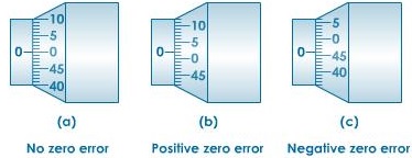
Positive Zero Error
If the zero marking on the thimble is below the datum line, the micrometer has a positive zero error. Whatever reading we take on this micrometer we would have to subtract the zero correction from the readings.
If the zero marking on the thimble is below the datum line, the micrometer has a positive zero error. Whatever reading we take on this micrometer we would have to subtract the zero correction from the readings.
Negative Zero Error
If the zero marking on the thimble is above the datum line, the micrometer has a negative zero error. Whatever readings we take on this micrometer we would have to add the zero correction from the readings.
Note: You do not have to memorise
positive error = subtract, negative error = add, just think this through for a while. It is rather straightforward and intuitive.
No comments:
Post a Comment